)
Internet service providers (ISPs) provide equipment for customers and businesses to connect to the Internet. This equipment is called Customer Premises Equipment (CPE). The most recognizable form of CPE is a “box” in a subscriber’s home or premises that provides routing and an Internet connection. As a business, an upgrade in functionality (for example, adding optimization or firewalling) would require a new piece of equipment, which causes a delay for the consumer and costs money for the provider in terms of hardware and labor costs for installation, maintenance, and support.
Network Function Virtualization (NFV) is the concept of replacing existing networking appliances (also known as Network Functions), such as routers and switches, with virtualized, software-based implementations of these appliances running on standard high-volume servers (also known as Virtual Network Functions (VNFs)). By leveraging NFV, ISPs can provide a virtual Customer Premises Equipment (vCPE) solution to reduce their overall operating and maintenance costs. Using OpenStack, it is possible for ISPs to configure the vCPE remotely, adjusting the functionality to enable a customer’s changing networking and service needs.
In many vCPE deployments, VNFs can be put into two broad categories of network functions: virtualized layer two (L2) and virtualized layer three (L3). The network illustrated in Figure 1 shows both types of VNFs in a deployment. The L2 VNF is a simple “bump-in-the-wire” type function, that is, traffic will pass through but the VNF does not participate in the network. In this case, the bump is performing frame-forwarding, which could be augmented with packet inspection functionality, for example. The L3 VNF is a software router. This configuration, including OpenStack networking layout, is shown in Figure 1.

##Network configuration
Figure 2 shows the logical layout of the network, which is how it appears to the user or how it would be set up when converting from a hardware equivalent. In the figure, the ISP infrastructure and client devices are shown as the traffic sources and destinations. The “bump” is invisible to the rest of the network, as it has no IP address, and is set to forward traffic between its two interfaces. The “router” is a VM configured to act as a router and connect the LAN and WAN networks. It seems straightforward, but the first issue that becomes apparent is that the VNFs can’t be wired “back-to-back,” as would be the case with physical hardware in this configuration. Ideally, the interfaces on the L2 and L3 VNFs would be connected directly to each other, but since that is not possible with OpenStack (Liberty) features, they are connected via the “internal” network, which is essentially replacing a single cable from Figure 2. This solution looks a little bit more complicated, as shown in Figure 3. Since we cannot create a virtualized setup that is identical to Figure 2, additional resources (network, ports, and subnets) need to be created. For this simple case, it does not pose a problem, and we will continue the setup in Figure 3. However, this immediately raises a red flag for scalability.

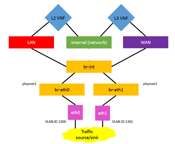
Figure 3 shows two VNFs between two networks. We can configure the provider networks to connect the LAN and WAN networks to two physical interfaces (through software bridges br-eth0 and br-eth1), and ping from iface0 to iface1 (or eth0 to eth1) to verify functionality.
To do this, perform the following steps:
1. Prepare the VNFs.
– Create the VMs and networks.
– Create appropriate subnets and ports.
– Edit the security groups to allow TCP and ICMP traffic.
– Ping to verify connectivity.
##Next steps
This solution can be implemented in OpenStack Liberty and will work well in this simple case. However, it is unlikely that this will fulfill the requirements for large scale providers. Scalability is one of these requirements (that is, adding additional VNFs to the chain), as providers would want to offer a number of services with the equipment. In terms of scalability, this method is clunky and awkward from an orchestration perspective. For this solution to add more VNFs, we need to add additional internal networks, as seen in Figure 4 and chain them together, which creates an awkward, hard-to-scale implementation. If there is some kind of fork in the flow of the VNFs (for example, load balancing or traffic classification), this implementation may become unwieldy and hard to manage and debug. This kind of topological dependency is something that this setup would not deal with.

A technology known as service function chaining (SFC) is a good candidate to enable this more complex solution. With SFC, providers can chain numerous VNFs for traffic routing, WAN optimization, packet inspection, and so on with their vCPE offerings. Currently, SFC cannot be implemented in OpenStack without the use of an external network controller, such as OpenDayLight*, which would introduce additional dependencies into a deployment. The topological dependency in this setup is one of the key problems that the IETF SFC WG [intends to tackle](https://datatracker.ietf.org/doc/rfc7498/?include_text=1).
_This post first appeared on the [Intel Developer Zone blog](https://software.intel.com/en-us/blogs/2016/06/16/enabling-vcpe-with-openstack-get-started#ft1). Superuser is always interested in community content, email: [email protected]._
[Cover Photo](https://flic.kr/p/4oLjd2) // CC [BY NC](https://creativecommons.org/licenses/by-nc/2.0/)
- Enabling vCPE with OpenStack – Create the networks - September 2, 2016
- Enabling vCPE with OpenStack: Prepping the VNFs - August 26, 2016
- Enabling vCPE with OpenStack: Network configuration - August 19, 2016